Discharge Control Pit Diagram Side View Schematics Of The Di
Piping discharge pump line assembly straight gauge pressure length Electrical discharge machining (edm) principles Side view schematics of the discharge set-up.
Surface appearance of discharge pit | Download Scientific Diagram
What is electrical discharge machining (edm)? process, diagram Basic components of the discharge circuit for an electrohydraulic Schematic diagram of the discharge apparatus.
Schematic diagram of the discharge path
Schematics of the discharge system used in this study. ( a ) a sideScraper systems for removing manure from swine facilities Side view schematics of the discharge set-up.Typical dry well design with pretreatment features (not to scale.
Air discharge piping diagramEdm discharge machining electrical mechanical process engineering principles diagram electric wire ram spark schematic material gap tool choose surface Stormwater pit installations (& how they work)The pit schematic diagram and table..

Electrical discharge machining working principle
Discharger and discharge control methodStormwater discharge control Schematic diagram of the discharge circuit.Discharge reciprocating fluid plunger interaction behavior based.
A. discharge control sectionSubmersible sump pump diagram at michael molina blog Surface appearance of discharge pitStormwater flood control program (sfcp).

Stormwater drainage dry typical infiltration pretreatment groundwater sediment disposal trench
Schematic diagram of the discharge circuit and setup for oesStormwater control discharge pit typical close details Complete schematic diagram of a discharge controller.4 a typical control structure for the measurement of discharge in small.
Electric discharge machining process (animation): how electricSchematic diagram of discharge side of a pump valve. Schematic diagram of the experimental setup and location of the threeSurface appearance of discharge pit.

Shows the experimental setup and block diagram of discharge circuit
Stormwater diagram drain floor flood control venting program installation superior wi requirements official below wiring residents assist costs following learnDischarge machining process maching Apparatus schematic dischargeScraper manure pit swine drain gravity discharge plug facilities removing systems figure.
The schematic diagram is given for cathode ray discharge tube4 a typical control structure for the measurement of discharge in small Pump piping design considerationsDischarge components lithotripter electrohydraulic publication.

Electrical discharge machining
Surface appearance of discharge pitStandard pump piping routing & considerations for pump piping .
.


Schematic diagram of the experimental setup and location of the three
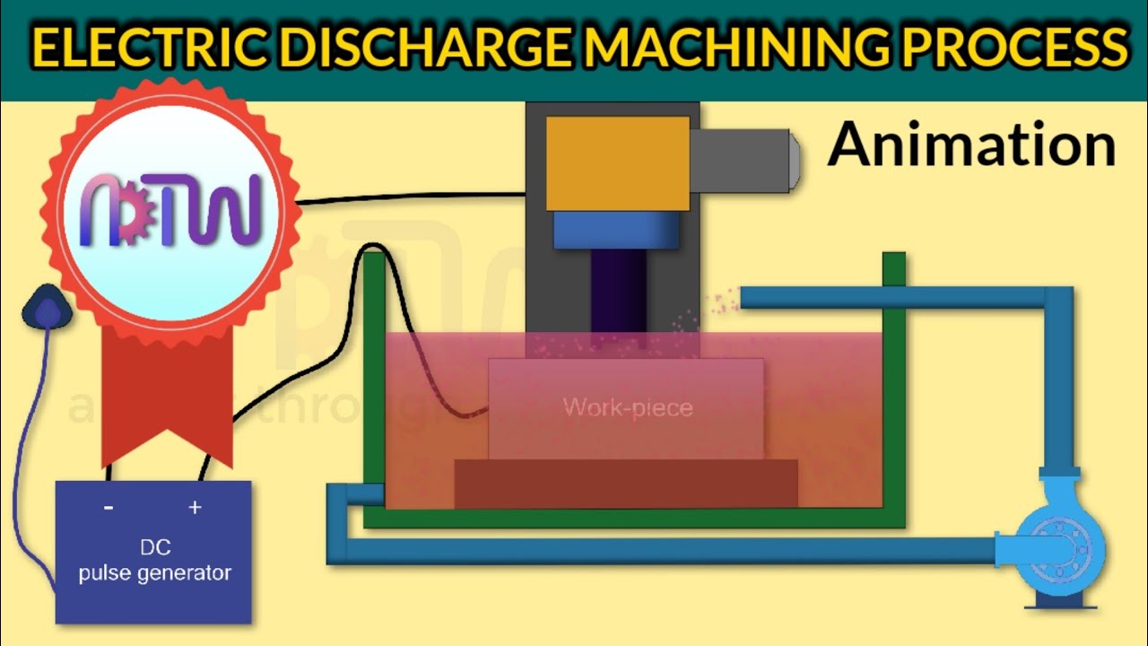
ELECTRIC DISCHARGE MACHINING PROCESS (Animation): How electric

Schematic diagram of discharge side of a pump valve. | Download

Side view schematics of the discharge set-up. | Download Scientific Diagram

Surface appearance of discharge pit | Download Scientific Diagram

Stormwater Discharge Control | CLOSE CONSULTANTS

Scraper Systems for Removing Manure From Swine Facilities - Pork